Rehousing a Tech 21 Double Drive pedal

What's Hot
JtaylorJtaylor Frets: 182
edited July 2016 in Making & Modding
So due to the case of my tech 21 double drive falling apart, (the base was being held on with one screw as the rest had snapped!) i decided to re house it, a technician at my uni offered to do it for me, and as i have no experience i took the opportunity, however after i received the pedal back from him i realised it needing fixing. @roland kindly helped me and managed to find that the holes for the jacks weren't large enough meaning they didn't fit through causing the circuit board to bend in order to making it fit. the holes for the jacks were also drilled at very different heights so even after reaming out the holes to fit the jacks the circuit board sits at a massive angle, resulting in the pots being at an ok height on one side but not able to properly reach through the enclosure on the other, he also took off the led to re drill the hole for the led as he drilled it on the wrong side! basically its going to need a whole new enclosure, the main issue is i don't know where the led goes back on the circuit board, does anyone have a schematic for it or a picture of where it is soldered to?

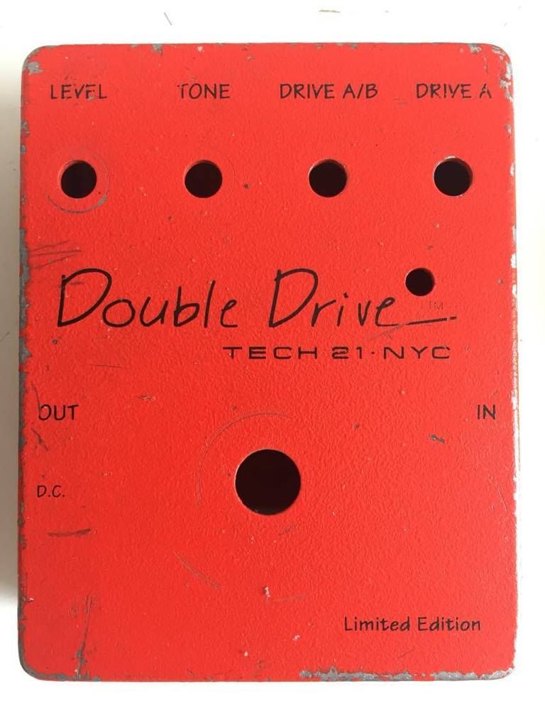
heres the original enclosure

image

Thanks in advance for any help
0reaction image LOL 0reaction image Wow! 0reaction image Wisdom

Comments

  • RolandRoland Frets: 8856
    Tech21 have been very helpful. They have provided a description of where the LED goes, and how best to install it. However the pedal has been discontinued for years so they can't provide a picture.

    Has anyone got a similar pedal? Could you take a picture of the circuit board?
    Tree recycler, and guitarist with  https://www.undercoversband.com/.
    0reaction image LOL 0reaction image Wow! 0reaction image Wisdom
  • markvmarkv Frets: 460
    I've got a Double Drive, black enclosure. I've taken it apart as much as I can but I'm blowed if I can see how to get the circuit board out of there. In fact I can't work out how they got it in there.

    I did my best with a photo, I know it's not very helpful, but you can (hopefully) just about see that there are 2 wires from the LED that go straight down to the board so my guess is that wherever it needs to connect to is pretty much right underneath the LED hole.

    0reaction image LOL 0reaction image Wow! 1reaction image Wisdom
  • ICBMICBM Frets: 73127
    edited June 2016
    Looks like it's the two solder pads below and slightly to the right of the right-hand terminal of the left-hand pot… if that makes sense!

    I would have though it would be fairly obvious from just looking at the PCB anyway.

    Make sure you get the LED the right way round, or it won't work. The 'flat' on the casing is on the left in that pic.


    I hope this "technician" is not in charge of maintaining anything important, by the way...

    "Take these three items, some WD-40, a vise grip, and a roll of duct tape. Any man worth his salt can fix almost any problem with this stuff alone." - Walt Kowalski

    "Only two things are infinite - the universe, and human stupidity. And I'm not sure about the universe." - Albert Einstein

    0reaction image LOL 0reaction image Wow! 0reaction image Wisdom
  • RolandRoland Frets: 8856
    Thanks @markv. That's where I thought the LED might go, and thanks @ICBM for spotting which way round it fits.

    The new case has been drilled. The holes are in the correct positions! Next job is to paint and label the case, which won't be finished until next week. After which there might be some pics.
    Tree recycler, and guitarist with  https://www.undercoversband.com/.
    0reaction image LOL 0reaction image Wow! 0reaction image Wisdom
  • RolandRoland Frets: 8856
    edited July 2016
    This afternoon I found time to reassemble, test, and make waterslide labels. Unfortunately I ran out of spray varnish, and it needs a coat to cover the waterslide labels. Here it is assembled, but not tightened down because I'll have to take it apart again to varnish it. Can anyone see this picture? https://goo.gl/photos/wA2uJ4VgdbhFNyBf7
    Tree recycler, and guitarist with  https://www.undercoversband.com/.
    0reaction image LOL 0reaction image Wow! 0reaction image Wisdom
  • RolandRoland Frets: 8856
    markv said:
    I've got a Double Drive, black enclosure. I've taken it apart as much as I can but I'm blowed if I can see how to get the circuit board out of there. In fact I can't work out how they got it in there.
    During manufacture the sockets are inserted first, then the loaded circuit board is placed on top of them, and the tags soldered. It is possible to get it out again. Unscrew everything, then push to the side so that the input socket slide further into its hole. That give just enough room to pull the other side of the circuit board assembly out.
    Tree recycler, and guitarist with  https://www.undercoversband.com/.
    0reaction image LOL 0reaction image Wow! 0reaction image Wisdom
  • JtaylorJtaylor Frets: 182
    Roland;1141145" said:
    This afternoon I found time to reassemble, test, and make waterslide labels. Unfortunately I ran out of spray varnish, and it needs a coat to cover the waterslide labels. Here it is assembled, but not tightened down because I'll have to take it apart again to varnish it. Can anyone see this picture?

    https://goo.gl/photos/wA2uJ4VgdbhFNyBf7

    Looks amazing @roland
    0reaction image LOL 0reaction image Wow! 0reaction image Wisdom
  • ICBMICBM Frets: 73127
    Great job.

    You just missed a bit...


    It should say 'VERY Limited Edition' at the bottom right :).

    "Take these three items, some WD-40, a vise grip, and a roll of duct tape. Any man worth his salt can fix almost any problem with this stuff alone." - Walt Kowalski

    "Only two things are infinite - the universe, and human stupidity. And I'm not sure about the universe." - Albert Einstein

    1reaction image LOL 0reaction image Wow! 0reaction image Wisdom
  • markvmarkv Frets: 460
    Roland said:
    markv said:
    I've got a Double Drive, black enclosure. I've taken it apart as much as I can but I'm blowed if I can see how to get the circuit board out of there. In fact I can't work out how they got it in there.
    During manufacture the sockets are inserted first, then the loaded circuit board is placed on top of them, and the tags soldered. It is possible to get it out again. Unscrew everything, then push to the side so that the input socket slide further into its hole. That give just enough room to pull the other side of the circuit board assembly out.
    On further examination that was my guess about how it was assembled (knowing little about these things). I'm not going to risk breaking it by trying to disassemble it!

    The finished article looks pretty good. Like @ICBM says - a very special edition!
    0reaction image LOL 0reaction image Wow! 0reaction image Wisdom
Sign In or Register to comment.